 QA Report
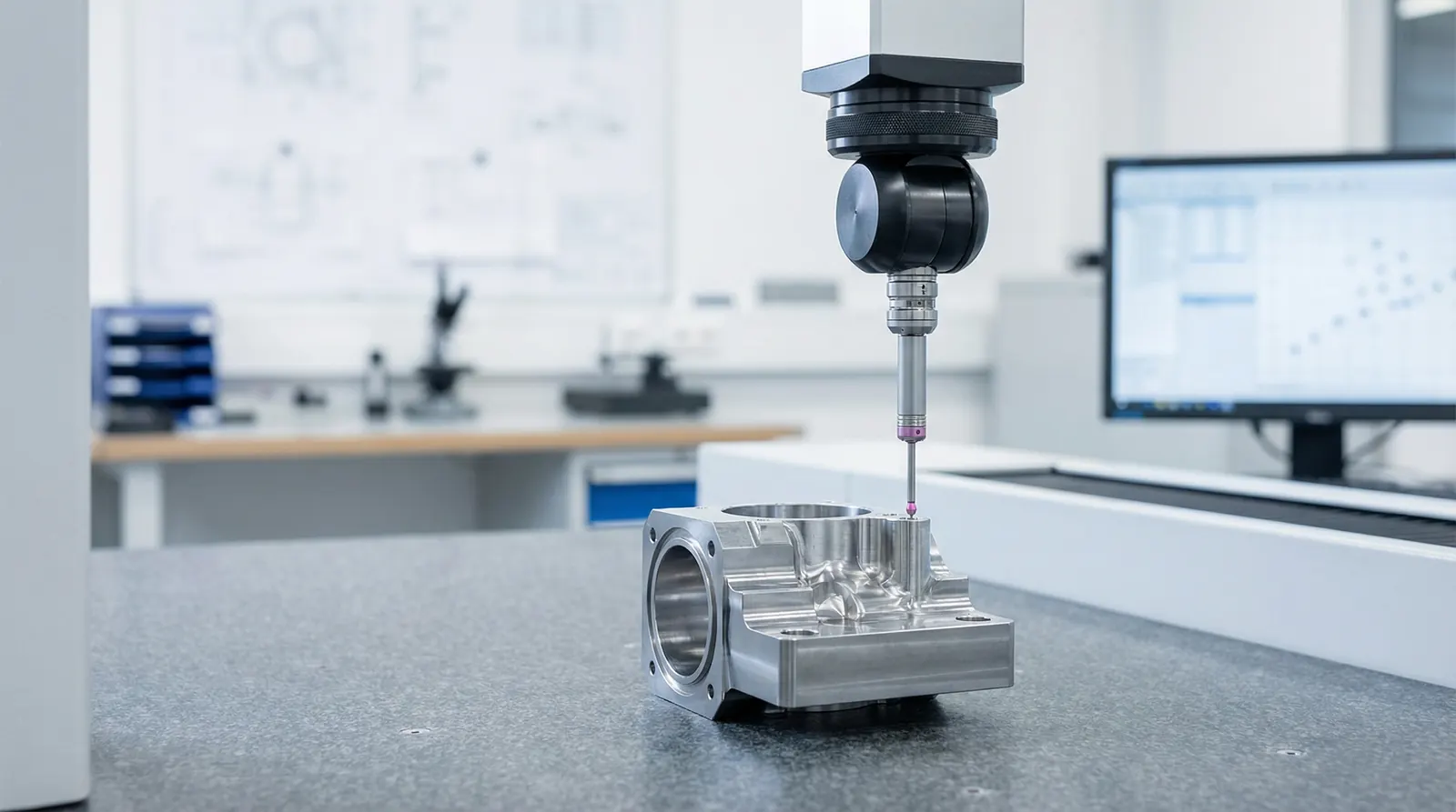

A coordinate measuring machine (CMM) is the backbone of dimensional inspection in precision manufacturing. If your shop makes parts to tight tolerances, understanding how CMM inspection works will help you write better programs, read reports with confidence, and catch problems before they reach the customer.
A CMM is a motorized measuring system that captures the X, Y, and Z coordinates of points on a part surface. By collecting enough points, the machine's software reconstructs features like holes, planes, cylinders, and complex contours, then compares each measured dimension to the nominal value on the drawing.
CMMs range from small benchtop units to gantry machines that can measure an entire engine block. Regardless of size, they all work the same way: a probe contacts or scans the part, the controller records each point's spatial coordinates, and the software evaluates the results against the part's tolerances.
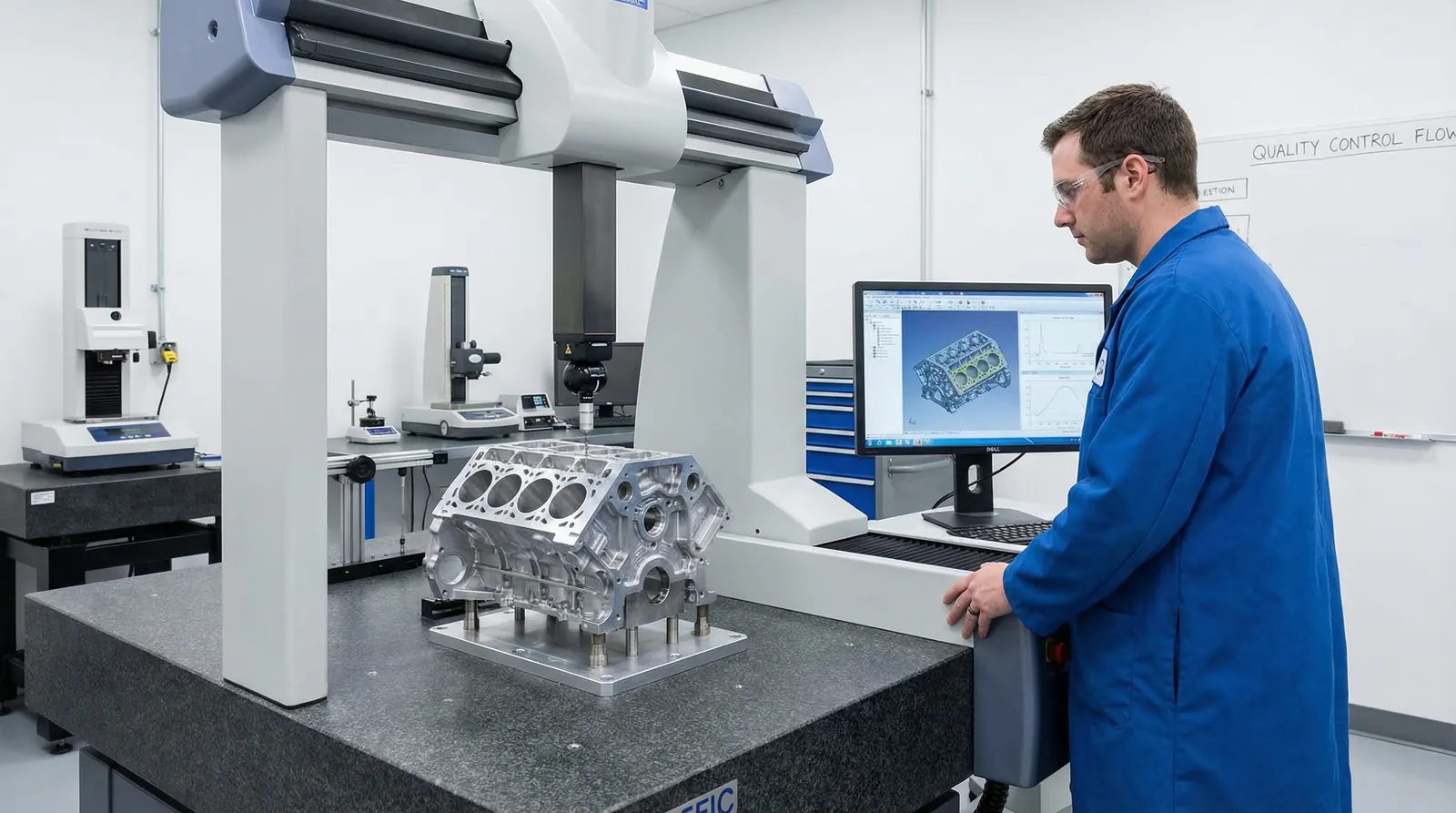
Before any measurement, the part must be held rigidly without distortion. Inspectors bolt fixtures to the CMM's granite table, clamp the part, and verify it is stable. A part that shifts even a few microns mid-run will produce unreliable data.
Every GD&T drawing defines datums: the reference features from which all measurements are taken. The CMM operator probes these datum features first to build a part coordinate system. If the datums are set up wrong, every measurement downstream will be offset, so this step demands care and verification.
Touch-trigger probes record a single point each time the stylus deflects. They are fast and reliable for discrete features like bore diameters, bolt-hole positions, and step heights. Scanning probes drag along the surface and collect thousands of points per second, which is necessary for evaluating form tolerances like roundness, cylindricity, or free-form profile.
Stylus selection matters too. A long stylus reaches recessed features but flexes more, reducing accuracy. Pick the shortest, stiffest configuration that can reach every feature in the program.
Production shops run CNC programs written in the CMM's native software (PC-DMIS, Calypso, MCOSMOS, and others). The program drives the probe to each feature automatically, measures it, and records the result. Manual or joystick inspection is still used for first-article work, prototype parts, or when a single dimension needs a quick check. Both approaches produce the same type of output: a list of measured features with their results.
A CMM report lists each measured feature with several columns:
Understanding these columns lets you make decisions quickly: accept, reject, rework, or adjust the machining process before the next run.
Geometric dimensioning and tolerancing (GD&T) defines not just size but form, orientation, and location. When a drawing calls out a position tolerance on a bolt-hole pattern, the CMM measures the center of each hole and evaluates how far it falls from the true position defined by the datums. The result is reported as a diameter zone, not a simple plus/minus value.
Profile tolerances work similarly: the CMM collects a dense set of points along a surface and compares the measured shape to the CAD model. Flatness, perpendicularity, runout, and concentricity each follow evaluation rules defined in ASME Y14.5 or ISO 1101, and the CMM software applies them automatically.
CMMs excel at discrete dimensional and GD&T features, but they are not always the best choice. Calipers and micrometers are faster for simple go/no-go checks on the shop floor. Optical comparators work better for thin, flexible parts or features like edge breaks that a touch probe cannot reach. 3D scanners capture full-surface geometry in seconds, which is more practical when you need to compare an entire casting to CAD. Surface roughness (Ra, Rz) requires a profilometer, not a CMM.
Most CMM software exports results as CSV, text, or proprietary file formats. QA Report imports these exports directly from Mitutoyo MCOSMOS, Zeiss Calypso, PC-DMIS, and other platforms. The software parses each measured dimension and matches it to the corresponding balloon number on your drawing.
This means you do not have to retype results into a spreadsheet. You balloon your drawing, import the CMM file, and the report populates automatically with nominals, tolerances, actuals, and pass/fail status for every characteristic. When you inspect multiple samples, each sample's data fills its own column so you can review the full batch in one document.
A well-structured CMM workflow starts with correct datum alignment, uses the right probe for each feature, and feeds results directly into your inspection documentation.
Import CMM results, match them to ballooned drawings, and generate audit-ready reports in minutes.
Try QA Report FreeCMM inspection is a precise, repeatable process, but its value depends on getting the fundamentals right: clean parts, correct datums, appropriate probing strategy, and a clear report that connects every measurement back to the drawing. Master these basics and the CMM becomes the most reliable quality gate in your shop.