 QA Report
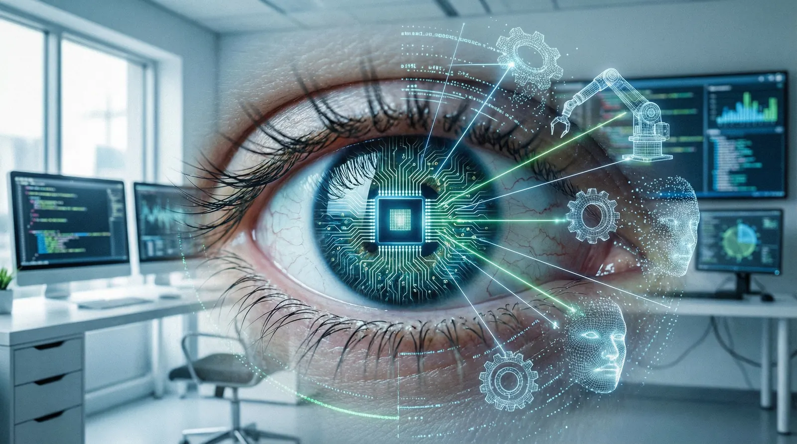

Machine vision puts a camera where a human eye used to be and a processor where judgment used to be. For quality engineers in machining and assembly, that trade matters: it changes what you can inspect, how fast, and at what cost.
A machine vision system has four core elements: a camera (area-scan or line-scan), a lens matched to the field of view and working distance, controlled lighting, and processing software that runs algorithms on the captured image.
The camera converts photons into a pixel array. The lens controls magnification and depth of field. The processor runs detection or measurement algorithms on that data and outputs a pass/fail decision, a measurement value, or a position command for a robot. These elements must be selected together; upgrading the camera without rethinking the lens or light rarely improves results.
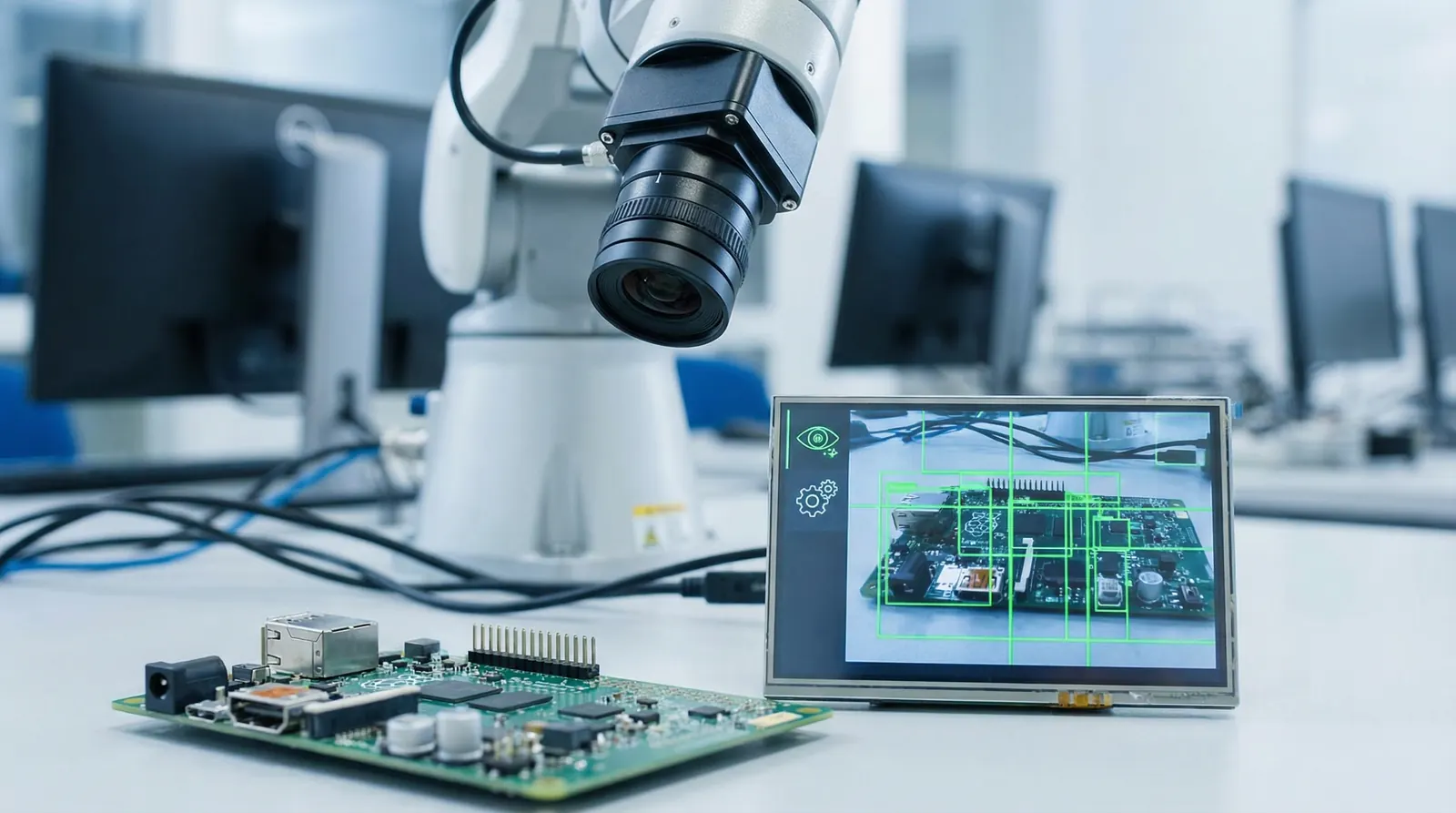
Lighting is the single most important variable. The same camera pointed at the same part produces unusable images under the wrong light. Bright-field illumination highlights surface texture; dark-field picks up scratches and edge defects. Backlighting silhouettes a part for precise edge measurement.
Most vision failures on the shop floor trace back to lighting changes: a bulb aging, ambient light shifting through the day, or a machined surface bouncing the source straight into the lens. Getting lighting right at installation and keeping it stable matters more than choosing a higher-resolution camera.
Vision excels at tasks that rely on contrast, edges, and patterns in a 2D image. The most common manufacturing applications include:
These tasks share a trait: the information the system needs lives in contrast boundaries within a single image frame. That is where vision is fast, repeatable, and cost-effective.

Vision struggles when the geometry leaves the image plane. Standard 2D cameras cannot measure depth, wall thickness, bore straightness, or features inside a cavity. Tight GD&T tolerances on 3D surfaces, such as true position of a hole pattern referenced to a datum on a different face, remain the domain of a CMM or structured-light scanner.
Reflective machined surfaces are another weak spot. A freshly milled aluminum face creates specular reflections that shift with minor changes in part orientation, making edge detection unreliable unless the lighting is engineered specifically for that finish.
Traditional machine vision is 2D: one camera, one image, measurements in X and Y only. 3D vision adds depth information through stereo cameras, structured light projection, or laser triangulation. 3D systems can measure height, flatness, volume, and surface profile, but they are slower per cycle, more expensive, and more sensitive to setup. For most in-line pass/fail checks, 2D vision is the practical choice. Reserve 3D for applications where the height dimension is the feature under inspection.
Classical machine vision uses rule-based algorithms: edge finders, pattern matchers, blob analyzers, and caliper tools configured by an engineer. These are deterministic and auditable. You know exactly why a part passed or failed, which matters when a customer asks for the inspection method on a PPAP submission.
Deep-learning vision trains a neural network on labeled images of good and defective parts. It handles complexity that rule-based tools cannot easily describe: irregular textures, cosmetic grading, or defects that vary in appearance. The trade-off is that the model is a black box, and retraining is needed when the part or finish changes. Many production systems now combine both: rule-based gauging for dimensions and deep learning for cosmetic classification on the same station.
A vision system used for dimensional measurement is a gauge, and it needs to be treated like one. That means calibrating the pixel-to-millimeter ratio with a certified standard, verifying distortion correction across the field of view, and running a gauge R&R study before trusting the numbers in production.
Temperature changes, vibration, and lens fouling all affect stability over time. A system that passed gauge R&R on Monday can drift by Friday if the environment is not controlled. Periodic verification with a known reference part, the same way you verify a micrometer or a CMM, keeps the system honest.
Vision and CMMs are complementary, not competing. A CMM measures 3D geometry with micrometer-level uncertainty and full GD&T capability but is slow and offline. Vision measures 2D features at production speed, in-line, on every part. A typical inspection plan uses vision for high-volume screening and routes a sample to the CMM for full-feature verification at lower frequency.
Both methods produce the same deliverable: a dimension-by-dimension pass/fail record tied to ballooned drawing features. Whether a diameter was measured by a vision caliper tool or a CMM probe, the result needs to appear on the inspection report against the correct balloon number, tolerance, and disposition.
Vision systems generate results at high speed, but those results still need to be documented the same way any measurement does: as individual values recorded against specific features on a ballooned drawing. Each camera measurement, whether it is a length, a gap, or a pass/fail presence check, maps to a balloon number, a nominal, a tolerance band, and a disposition.
QA Report keeps this traceability intact. Every measured value, regardless of the instrument that produced it, is stored against the ballooned feature it belongs to. The platform's drawing ballooning tool uses image recognition to detect dimensions on a drawing automatically, so setting up the inspection sheet does not require manual transcription of every callout. Once the balloons are placed, vision results, CMM results, and manual gauge readings all flow into the same report structure.
Whether your data comes from a vision system, a CMM, or a hand gauge, QA Report ties every value to a ballooned drawing feature in one audit-ready report.
Try QA Report FreeMachine vision is a fast, repeatable inspection tool that earns its place on any line where 2D features, surface quality, or part identification need to be checked at production speed. It does not replace a CMM for tight 3D tolerances, and it demands serious attention to lighting and calibration. Treat it as a gauge, verify it like a gauge, and record its output the same way you record every other measurement: against a ballooned feature, with a tolerance, in a structured report.