 QA Report
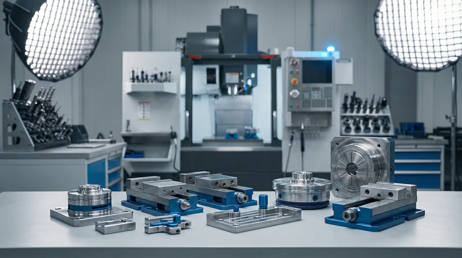

Your CNC program can be perfect, your tooling fresh, and your speeds and feeds dialed in. None of it matters if the workholding lets the part move, flex, or distort under cutting forces. Workholding is the foundation that every other machining decision rests on.
Rigidity keeps the part where the tool expects it. Any compliance in the fixture translates directly into dimensional error, chatter marks, or worse. A part that shifts by even 0.02 mm during a finishing pass will show that shift on every feature cut after the move.
Repeatability matters when you run more than one part. If every load cycle puts the part in a slightly different position, your process capability suffers even when individual pieces measure fine. The fixture must locate the part the same way every time, not just hold it firmly.
Distortion is the quieter problem. Thin-walled parts, castings, and long slender shafts all deflect under clamping pressure. The part may machine to perfect dimensions while clamped, then spring back out of tolerance when released. If you only inspect while the part is still fixtured, you will miss this entirely.
The standard milling vise is the workhorse of CNC work. For prismatic parts with at least two parallel faces, a quality vise with hardened jaws delivers excellent rigidity with minimal setup time. Soft jaws, machined to match the part profile, extend this approach to contoured or round parts. They spread clamping force over a larger contact area and reduce the risk of marking finished surfaces.
Dovetail workholding machines a dovetail profile into the raw stock, then clamps on that profile. The approach gives full top-face access for 3-axis work and holds the part with very little material extending above the jaws. It works well for low-profile parts that need machining on five of six sides in two operations.
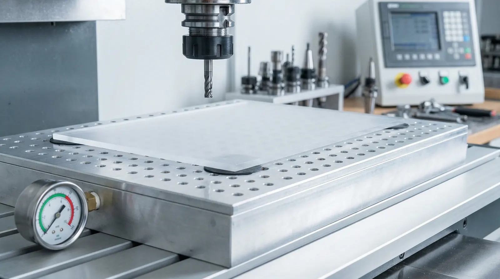
Vacuum chucks suit thin, flat parts where any side clamping would cause distortion. They apply uniform holding force across the entire bottom face. The limitation is that cutting forces must stay low enough that the vacuum can resist them, so these fixtures favor light finishing cuts and engraving. Magnetic chucks serve a similar role for ferrous materials and are standard in surface grinding, but the same force limitations apply.
Fixture plates with a grid of threaded and dowel holes let you bolt down clamps, stops, and locators in any arrangement. Combined with a zero-point clamping system, the entire fixture can be removed from and returned to the machine with repeatability under 0.005 mm. This is essential in high-mix shops where changeover time directly affects throughput.
When part geometry does not suit any standard workholding, a dedicated fixture is the answer. This can range from a simple machined nest to a complex hydraulic tombstone loaded with multiple parts. The upfront cost is higher, but for production runs the payoff is faster load and unload cycles and consistent part location across hundreds or thousands of pieces.
Five-axis machining adds a constraint: the fixture must not interfere with the tool or spindle head as the part rotates. Dovetail holders, low-profile vises, and purpose-built trunnion fixtures all address this. The goal is maximum access to the part surfaces while keeping the setup rigid enough to handle cutting loads at every orientation.
The fixture should locate the part on the same datums called out on the drawing. When machining datums and inspection datums match, every measurement taken on the CMM or at the machine reflects what the drawing actually controls.
When they do not match, you introduce datum shift: the measured values depend on which surfaces the part sat on during inspection, and the numbers change if you flip the part to a different setup. This makes it difficult to separate real machining error from measurement variation caused by the fixture.
Before building or ordering a fixture, review the GD&T callouts and confirm that the primary, secondary, and tertiary datum features can serve as locating surfaces in the fixture. If a datum feature is machined in a later operation, plan the sequence so that the datum is established before the features controlled by it are cut.
More clamping force is not always better. Over-clamping thin or flexible parts causes them to conform to the fixture under pressure, machine to nominal while distorted, and then spring back out of tolerance when released.
The test is straightforward: measure the part while it is still clamped, then measure it again after unclamping. If the numbers change beyond your tolerance budget, reduce clamping force or redesign the fixture to support the part closer to where the tool is cutting.
For critical parts, consider:
The first part off a new setup should always get a full inspection before the rest of the batch runs. This first-article inspection validates that the fixture is locating the part correctly, the program offsets are right, and the tooling is cutting to size.
During the production run, periodic in-process checks catch drift from tool wear, thermal growth, or fixture loosening. The features you check in-process should be the ones most sensitive to fixture position, typically the tightest tolerances and the features controlled by the primary datum.
Even a well-designed fixture fails if the basics are neglected:
When a fixture or setup problem causes dimensional drift, it rarely shows up as a single bad measurement. It appears as a pattern: the same feature running high across multiple parts, or a position tolerance shifting after a fixture changeover.
QA Report ties every inspection result to the batch and route card, so you can filter by setup, fixture, machine, or operator and see whether a trend is isolated or systemic. Instead of chasing individual out-of-tolerance readings, you trace the pattern back to its source, whether that is a worn fixture, a shifted locating pin, or a program offset that needs correction.
That traceability turns reactive quality firefighting into process control. When the data is structured and searchable, you catch a fixture problem at the first-article stage rather than at final inspection of a full batch.
Link every measurement to its setup, fixture, and batch. Spot patterns before they become scrap.
Try QA Report Free