 QA Report
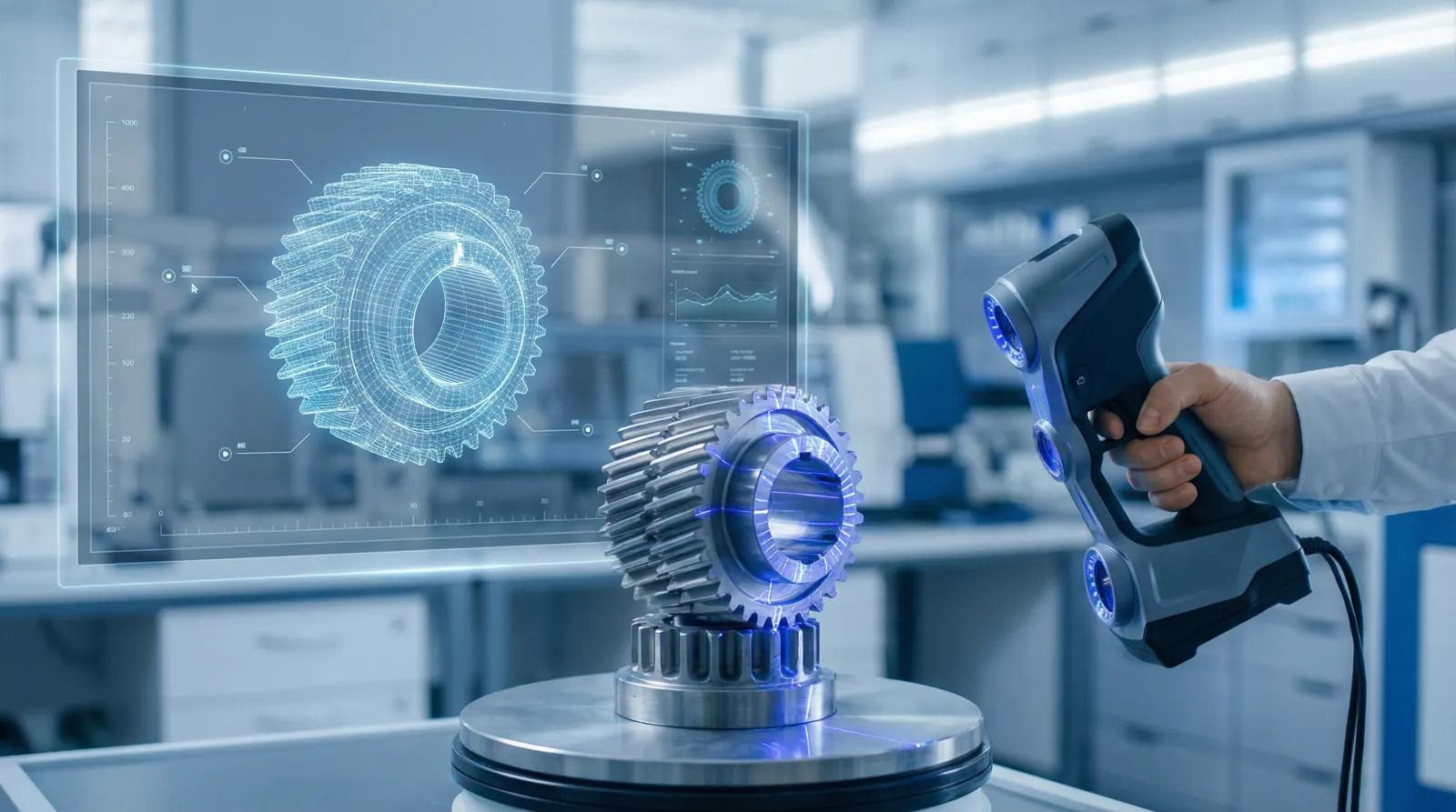

Quality engineers adopting 3D scanning for part inspection gain full-surface data that traditional gauges and even CMMs cannot practically deliver. But scanning is not a universal replacement. Understanding where it excels and where it does not is essential for choosing the right method.
Two dominant technologies serve manufacturing inspection: structured-light scanners and laser-line scanners.
A structured-light scanner projects a pattern of parallel fringes onto the part. Cameras observe the distortion of that pattern from a known angle, and software triangulates each pixel to a 3D coordinate, producing millions of points per exposure.
A laser-line scanner sweeps a thin laser stripe across the surface while a camera records the stripe's deformation. Line scanners are commonly mounted on CMM arms or robotic systems, combining the flexibility of contact probing with non-contact speed.
Both technologies produce a point cloud: a dense set of XYZ coordinates representing the scanned surface. Software converts the point cloud into a triangulated mesh, a continuous surface of small triangles that can be compared to the nominal CAD model.
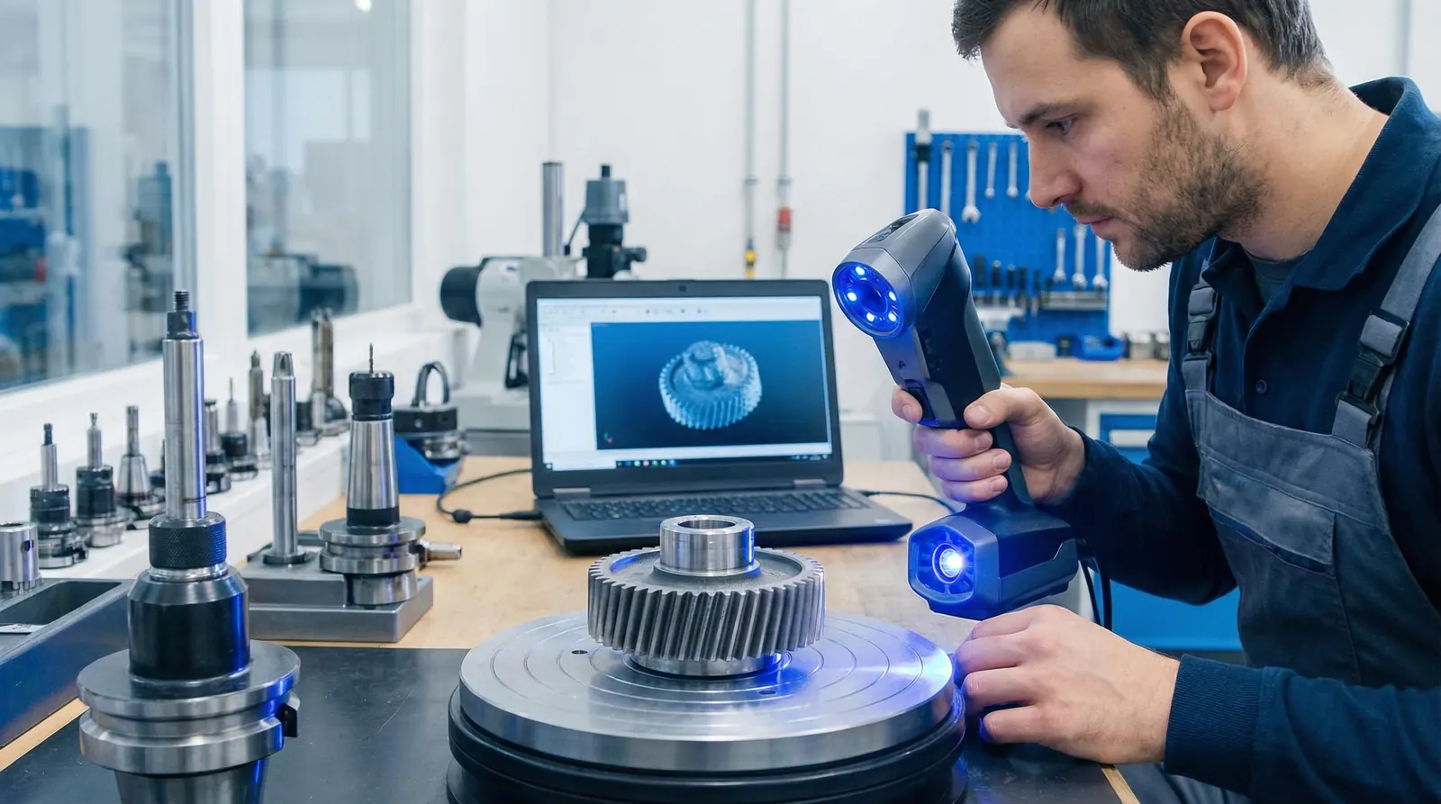
The most common use of scan data is a full-surface deviation map. Inspection software aligns the mesh to the CAD model, then calculates the perpendicular distance from every mesh point to the nearest CAD surface. The result is a color map painted onto the 3D model: green for in-tolerance areas, graduating to yellow, orange, and red as the deviation grows. This view immediately highlights warpage, tool wear, or areas where material is missing or proud.
Inspection software can also extract discrete dimensions from the mesh. An operator picks features (planes, cylinders, spheres), and the software fits geometric primitives to compute diameters, distances, angles, and GD&T callouts. These values are derived from thousands of mesh points per feature rather than a handful of contact points.
3D scanning is strongest in situations where a CMM is either impractical or too slow:
Scanning is not the right tool for every measurement:
Use scanning for full-surface coverage, complex geometry, and speed. Fall back on the CMM or hand gauges for tight-tolerance bores, threads, and datum-critical GD&T.
A practical shop-floor scanning session follows a predictable sequence:
However a part is measured, the end product is the same: a list of dimensions, each compared to its nominal value and tolerance, with a clear pass or fail verdict. Whether a number came from a CMM, a hand caliper, or an extracted scan feature, it occupies one row in the inspection report, tied to a balloon number on the drawing.
This is where tools like QA Report's inspection software close the loop. Engineers balloon the drawing to assign a unique identifier to each feature, then record measured values from any source: CMM output, caliper readings, or scan-extracted dimensions. The report captures who measured, when, with what instrument, and whether the result is within tolerance. Mixing sources in one report is routine, because no single method covers every feature on a complex part.
CMM, scanner, hand gauge: QA Report tracks them all against your ballooned drawing, with tolerance validation and audit-ready documentation.
Try QA Report Free3D scanning is a powerful addition to the quality engineer's toolkit, not a wholesale replacement for existing methods. Use it where it shines: full-surface coverage, complex geometry, and fast turnaround. Fall back on the CMM or hand gauges for the features that demand it. The inspection report stays the same either way: every dimension accounted for, every tolerance evaluated, every result traceable.