 QA Report
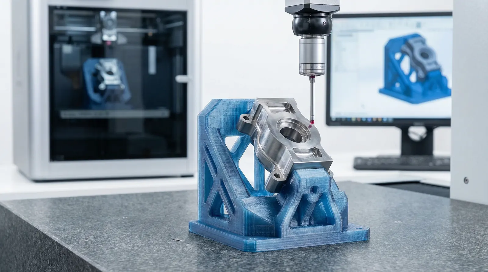
A CMM measurement is only as good as the fixture holding the part. 3D printing gives quality teams a fast, affordable way to build conformal nests that keep datum targets exposed and probes unobstructed.
Every coordinate measuring machine program assumes the part sits in a known orientation with its datum features accessible. If the fixture distorts the part, shifts between measurements, or blocks the probe from reaching a critical surface, the numbers on the report are meaningless. Good part holding does three things at once: it locates the part so datum alignment is repeatable from one piece to the next, it gives the probe stylus clear access to every feature called out on the drawing, and it does both without clamping hard enough to deform thin walls or flexible geometry.
Universal clamp kits handle simple prismatic parts well. But castings, investment-cast turbine blades, plastic housings, and machined freeform surfaces often sit awkwardly in vee-blocks and strap clamps. The programmer spends time shimming and adjusting, and the operator repeats that effort every time the job comes back. This is where a dedicated, conformal nest pays off.
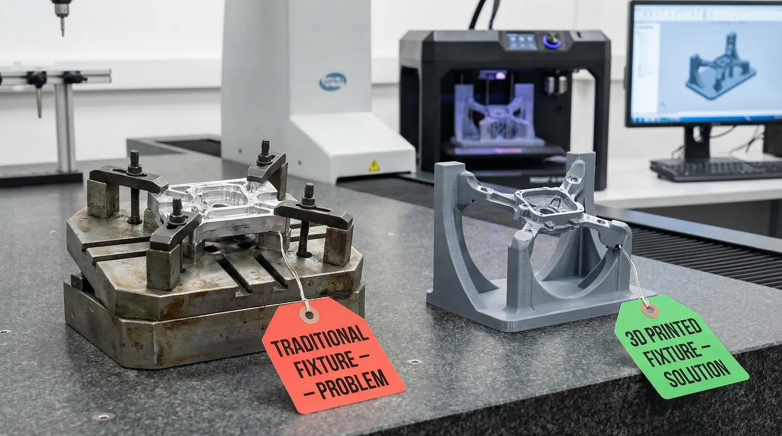
A printed nest wraps around the part geometry rather than forcing the part into a generic clamp. Because the nest is modeled from the same CAD used to program the CMM, it can cradle complex contours, locate on specific cast features, and leave every GD&T datum target fully exposed. The key advantages are practical, not theoretical:
The most common mistake is building a nest that holds the part perfectly but blocks the probe from reaching a bore or an undercut. Before printing, run a collision check in your CMM software or at least review the probe path visually. Leave generous relief around any surface the program needs to touch, and remember that the probe body and the stylus holder need clearance too, not just the tip.
Keep the primary, secondary, and tertiary datum targets exposed. The nest should support the part from the opposite side or from non-datum surfaces. If the drawing calls out a datum target on the bottom face, the fixture must contact only outside that target zone and leave the target itself open for a reference measurement.
Avoid pockets and enclosed channels where machining chips, coolant residue, or dust can collect and push the part out of position. Add drain slots or open the bottom of the nest so debris falls through. In a production environment, fixtures that trap contamination cause intermittent measurement shifts that are difficult to diagnose.
A nest that flexes under the part's weight will not hold position reliably. Add ribs on the underside, increase wall thickness to at least 3 to 4 mm, or use a honeycomb infill at high density. The nest does not need to be solid, but it does need to resist deflection under load without creeping over time.
Design bolt holes or alignment pins so the nest attaches firmly to the CMM granite table, a modular fixture plate, or a magnetic chuck plate. A nest that slides when the probe contacts the part defeats the purpose. Counterbored holes for M6 or M8 bolts work well and are easy to print accurately.
Most shops start with PLA because it is easy to print and stiff enough for light parts. For heavier parts or tighter repeatability, consider the following:
Avoid any material that creeps (slowly deforms) under sustained clamping pressure. If a fixture is bolted down under tension and the bolt gradually sinks into the plastic, the part shifts. Printing with higher infill and using washers under bolt heads helps, but switching to a stiffer filled filament is the more reliable answer. Temperature matters too: a CMM lab is climate-controlled, but if fixtures ever sit in a warm shipping area or near a machine tool, PLA can soften and lose its shape above about 55 degrees Celsius.
Print a test coupon alongside your first fixture and measure it periodically. If the coupon dimensions drift, the fixture is drifting too.
Before trusting a new printed nest for production measurements, run a short repeatability study. Place a known-good part in the nest, measure it, remove it completely, replace it, and measure again. Repeat this at least five times. Compare the spread in your results to the tolerance on the drawing. If the fixture-induced variation eats up more than a small fraction of the tolerance band, redesign the nest for a tighter fit or add a positive locating feature such as a pin or a lip.
Re-check the fixture after a few months of use. Printed plastics can wear at contact points, especially if parts have sharp edges or burrs. A worn nest that has opened up by a tenth of a millimetre may not hold the part in the same position it did on day one. Keeping the original CAD file and the print settings makes reprinting a replacement straightforward when the time comes.
Printed nests are not a universal replacement. Machined aluminum or steel fixtures remain the better choice when the part is heavy enough to deflect a plastic nest, when the fixture must survive thousands of load-unload cycles on an automated CMM cell, or when the operating environment involves temperature swings that would distort plastic. Modular fixture systems with their grid plates and adjustable risers also offer value when fixture changeover speed matters more than conformal fit, and when the same set of components can be reconfigured for dozens of different parts without printing anything new.
The practical answer for most quality departments is a mix: modular hardware for high-volume prismatic parts, machined fixtures for heavy or high-cycle applications, and printed nests for everything that falls in between.
Traceability does not stop at the measurement data. When a customer or an auditor asks how a part was held during inspection, the answer should be in the report, not in someone's memory. Recording the fixture ID, a photo of the setup, and any special instructions (such as torque on hold-down bolts) ties the measurement results back to the exact holding method used. If a printed fixture is later found to have worn or shifted, you can identify which reports were generated with that fixture and decide whether re-inspection is needed.
In QA Report, custom report fields let you capture the fixture identifier, the holding method, and setup notes directly on the inspection report. This keeps the information alongside the dimensional data rather than in a separate log, making it easy to retrieve during audits or customer inquiries.
Capture fixture details, measurement data, and traceability in one place.
Try QA Report Free3D-printed fixtures fill a gap that universal clamps and machined nests leave open: affordable, conformal part holding for complex geometries, small batches, and first-article inspection. Design them with probe clearance and datum exposure in mind, choose a material stiff enough for the job, and validate repeatability before trusting the results. Combined with proper fixture documentation on your inspection reports, printed nests give CMM programmers a practical tool that cuts setup time without sacrificing measurement confidence.